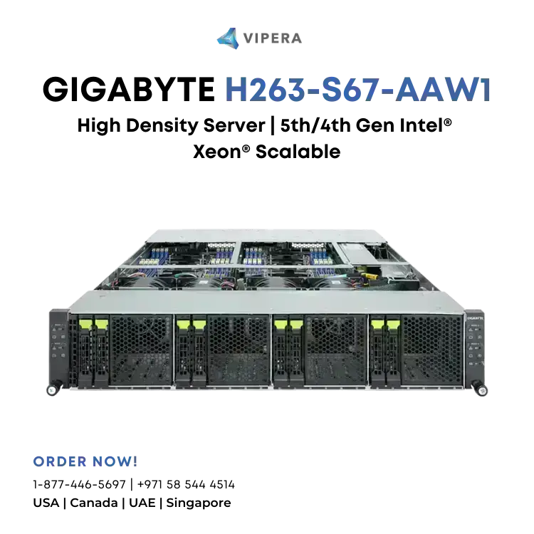
High Density Server – 5th/4th Gen Intel® Xeon® Scalable – 2U 4-Node DP 8-Bay Gen5 NVMe/SATA/SAS-4 3000W
2U 4-node rear access server system
Dual 5th/4th Gen Intel® Xeon® Scalable Processors per node
Dual Intel® Xeon® CPU Max Series per node
8-Channel DDR5 RDIMM, 64 x DIMMs
Dual ROM Architecture
1 x CMC port
8 x 2.5″ Gen5 NVMe/SATA/SAS-4 hot-swappable bays
4 x M.2 slots with PCIe Gen4 x4 interface (optional)
4 x LP PCIe Gen5 x16 slots
4 x OCP 3.0 Gen5 x16 slots
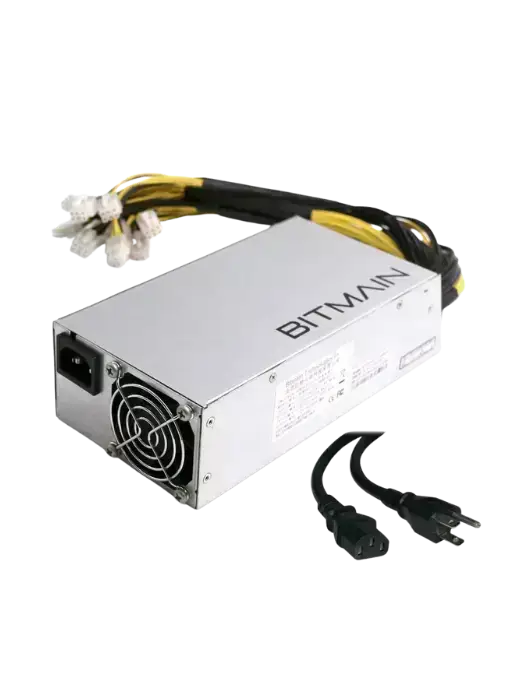
Dual 3000W 80 PLUS Titanium redundant power supply
Dimensions (WxHxD, mm) | Expansion Slots | Power Supply |
2U 4-Node – Rear access | Per node: | Dual 3000W 80 PLUS Titanium redundant power supply |
440 x 87.5 x 840 | Riser Card CRSH01U: | Available for 2+1 redundant power supply configuration (optional) |
Motherboard | – 1 x PCIe x16 (Gen5 x16) low-profile slot, from CPU_0 | |
MS63-HD1 | AC Input: | |
CPU | 1 x OCP 3.0 slot with PCIe Gen5 x16 bandwidth, from CPU_0 | – 100-127V~/ 16A, 50/60Hz |
5th Generation Intel® Xeon® Scalable Processors | Supports NCSI function | – 200-207V~/ 16A, 50/60Hz |
4th Generation Intel® Xeon® Scalable Processors | – 208-240V~/ 16A, 50/60Hz | |
Dual processor per node, TDP up to 270W | Optional 1 x M.2 slot (CMTP061): | |
– M-key | DC Input: (Only for China) | |
Supports TDP up to 350W with no support on OCP slot at ambient 35°C. | – PCIe Gen4 x4, from CPU_1 | – 240Vdc/ 16A |
– Supports 2280/22110 cards | ||
Supports TDP up to 350W at ambient 30°C. | DC Output: | |
Total: | – Max 1200W/ 100-127V~ | |
Note: If only 1 CPU is installed, some PCIe or memory functions might be unavailable. | Riser Card CRSH01U x 4: | #ERROR! |
Socket | – 4 x PCIe x16 (Gen5 x16) low-profile slots, from CPU_0 | #ERROR! |
Per Node: | – Max 2600W/ 200-207V~ | |
2 x LGA 4677 | 4 x OCP 3.0 slots with PCIe Gen5 x16 bandwidth, from CPU_0 | #ERROR! |
Support NCSI function | #ERROR! | |
Total: | – Max 3000W/ 208-240V~ or 240Vdc Input | |
8 x LGA 4677 | Optional 4 x M.2 slots (CMTP061): | #ERROR! |
– M-key | #ERROR! | |
Socket E | – PCIe Gen4 x4, from CPU_1 | |
Chipset | – Support 2280/22110 cards | Note: The system power supply requires C19 power cord. |
Intel® C741 | Internal I/O | System Management |
Memory | Per node: | Aspeed® AST2600 management controller |
Per node: | 1 x TPM header | GIGABYTE Management Console (AMI MegaRAC SP-X) web interface |
16 x DIMM slots | 1 x VROC connector | |
Front I/O | Dashboard | |
Total: | Per node: | HTML5 KVM |
64 x DIMM slots | 1 x Power button with LED | Sensor Monitor (Voltage, RPM, Temperature, CPU Status …etc.) |
1 x ID button with LED | Sensor Reading History Data | |
DDR5 memory supported only | 1 x Reset button | FRU Information |
8-Channel memory architecture | 1 x System status LED | SEL Log in Linear Storage / Circular Storage Policy |
RDIMM up to 96GB supported | Hardware Inventory | |
3DS RDIMM up to 256GB supported | Total: | Fan Profile |
4 x Power buttons with LED | System Firewall | |
5th Gen Intel® Xeon®: Up to 5600 MT/s | 4 x ID buttons with LED | Power Consumption |
4th Gen Intel® Xeon®: Up to 4800 MT/s | 4 x Reset buttons | Power Control |
Intel® Xeon® Max Series: Up to 4800 MT/s | 4 x System status LEDs | Advanced power capping |
LAN | *1 x CMC status LED | LDAP / AD / RADIUS Support |
Per node: | *1 x CMC reset button | Backup & Restore Configuration |
1 x 10/100/1000 Mbps Management LAN | Remote BIOS/BMC/CPLD Update | |
*Only one CMC status LED and reset button per system. | Event Log Filter | |
Total: | Rear I/O | User Management |
4 x 10/100/1000 Mbps Management LAN | Per node: | Media Redirection Settings |
*1 x CMC port | 2 x USB 3.2 Gen1 | PAM Order Settings |
1 x VGA | SSL Settings | |
*Please refer to optional parts for ring topology support. | 1 x MLAN | SMTP Settings |
1 x ID button with LED | OS Compatibility | |
Note: Spanning Tree Protocol (STP) must be enabled on LAN switches when using a ring topology. | Please refer to OS compatibility table in support page | |
Video | Total: | System Fans |
Integrated in Aspeed® AST2600 | 8 x USB 3.2 Gen1 | 4 x 80x80x80mm (16,500rpm) |
2D Video Graphic Adapter with PCIe bus interface | 4 x VGA | Operating Properties |
1920×1200@60Hz 32bpp | 4 x MLAN | Operating temperature: 10°C to 35°C |
4 x ID buttons with LED | Operating humidity: 8-80% (non-condensing) | |
Management chip on CMC board: | *1 x CMC port | Non-operating temperature: -40°C to 60°C |
Integrated in Aspeed® AST2520A2-GP | Non-operating humidity: 20%-95% (non-condensing) | |
Storage | *Only one CMC port per system. | Packaging Dimensions |
Per node: | Backplane Board | 1180 x 779 x 300 mm |
2 x 2.5″ Gen5 NVMe/SATA/SAS-4 hot-swappable bays, from CPU_1 | Speed and bandwidth: | Packaging Content |
PCIe Gen5 x4 or SATA 6Gb/s or SAS-4 24Gb/s | 1 x H263-S67-AAW1 | |
Total: | TPM | 8 x CPU heatsinks |
8 x 2.5″ Gen5 NVMe/SATA/SAS-4 hot-swappable bays, from CPU_1 | 1 x TPM header with SPI interface | 24 x Carriers |
– Optional TPM2.0 kit: CTM010 | 1 x 3-Section Rail kit | |
SAS card is required for SAS devices support | Part Numbers | |
SAS | – Barebone package: 6NH263S67DR000ABW1* | |
Depends on SAS add-in cards | – Motherboard: 9MS63HD1UR-000 | |
RAID | – 3-Section Rail kit: 25HB2-A66125-K0R | |
Intel® SATA RAID 0/1/10/5 | – CPU heatsink: 25ST1-453200-A0R/25ST1-453208-C1R | |
– Front panel board – CFPH004: 9CFPH004NR-00 | ||
– Backplane board – CBPH081: 9CBPH081NR-00 | ||
– Fan module: 25ST2-888020-S1R | ||
– Riser card – CRSH01U: 9CRSH01UNR-00 | ||
– LAN board – CLBH010: 9CLBH010NR-00 | ||
– Power supply: 25EP0-230009-L0S | ||
Optional parts: | ||
– C19 power cord 125V/15A (US): 25CP1-018000-Q0R | ||
– C19 power cord 250V/16A (EU): 25CP3-01830H-Q0R | ||
– C19 power cord 125V/15A (JP): 25CPA-01830B-Q0R | ||
– M.2 riser card – CMTP061: 9CMTP061NR-00 | ||
– Ring topology kit (10-kit package): 6NH263S62S1000AAN11 | ||
– RMA packaging: 6NH263S67SR-RMA-A100 |
* The entire materials provided herein are for reference only. GIGABYTE reserves the right to modify or revise the content at anytime without prior notice.
* Advertised performance is based on maximum theoretical interface values from respective Chipset vendors or organization who defined the interface specification. Actual performance may vary by system configuration.
* All trademarks and logos are the properties of their respective holders.
* Due to standard PC architecture, a certain amount of memory is reserved for system usage and therefore the actual memory size is less than the stated amount.
No reviews available.